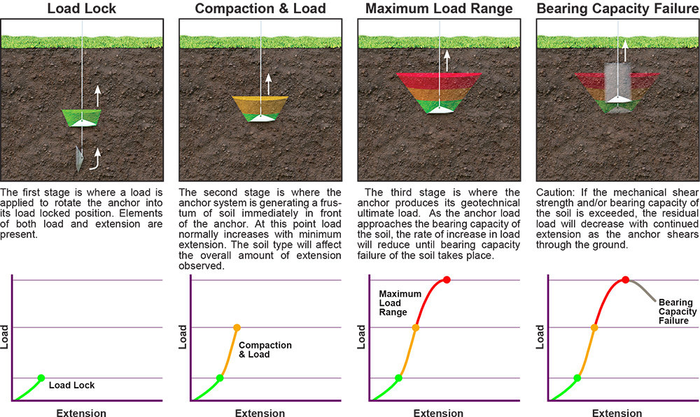
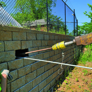
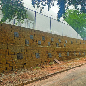
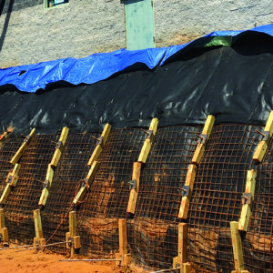
These anchors are intended for use in soil conditions for moderately loaded anchoring requirements. WFEC Soil Anchors use a tipping plate which is dependent upon the strength of the soil in order to react tensile loads. Anchors are driven into soil to a specified depth using special drive steel which is adaptable to percussion driving equipment, (i.e. jackhammer, concrete breaker or similar). The drive steel is removed and the anchor is tipped into place and proof tested with Williams’ Anchor Locking Kit by pulling on the anchor rod. This is called “load locking” and provides an immediate proof test of each anchor’s holding capacity. Interested customers should contact their local Williams technical representative in order to evaluate the appropriate anchor for each specific project.
Advantages
- Fast, easy installation
- Immediate proof test results
- No grout
- Inexpensive installation equipment
- Environmentally friendly
- No drilling required
Applications
- Retaining Walls
- Slope Stabilization
- Bridges
- Sheet Piling
- Gabion Support
- Buoyancy Control
- Guyed Structures
- Scaffolding
- Foundations
- Portable Buildings
- General Security
- Marine Applications
- Temporary Shoring
- Utility Poles
- Seawalls
- Pipelines
- Erosion Control
- Underwater Applications

The Platipus® Earth Anchoring Systems offer anchors with available tensile loading up to 44,000 lbs. These anchors are made from spheroidal graphite cast iron and are galvanized for superior corrosion protection. They are manufactured by a NAFTA free trade country and may meet domestic requirements on publicly funded projects. Platipus “Stealth” Anchors are used for lower load applications and numerous termination options are available. Platipus “BAT” anchors achieve higher loads, utilize a unique “T-knuckle” pivoting attachment point, and utilize Williams’ Grade 75 All-Thread Rebar, couplings, hex nuts and other accessories necessary for load transfer. Williams’ robust course thread pattern used on the All-Thread Rebar is extremely durable during anchor driving and eliminates the concern for thread chasing often required when using NC thread pattern anchor rods. All products are available galvanized upon request.
Typical Anchor Behavior

Platipus BAT Anchors
The ‘Bat’ anchor is designed to achieve higher loads than the Stealth Anchor product line, and enhance anchoring in soft cohesive soils. Their ability to accept the pivoting T-knuckle allows flexibility with regard to anchor rod size. It can be used with #6, #7, or #8 Grade 75 All-Thread Rebar. Please note #8 bar requires the T-knuckle to be externally threaded and uses a coupler for the connection to the #8 bar. Installation requires powerful hand-held hydraulic breakers or, in some cases, an excavator with a percussive breaker attachment.

BAT Anchor Structural Properties
| Anchor Type |
Dimensions L x W x H |
Projected Surface Area | Typical Load Range* |
Minimum Driven Depth |
Anchor Rod | |
|---|---|---|---|---|---|---|
| Diameter | Part Number |
|||||
| B4 | 12.2” x 4.3” x 3.6” (310 x 110 x 93 mm) |
~44.33 in2 (286 cm2) |
4.4 – 13.2 kips (20 – 60 kN) |
5’ – 8’ (1.5 – 2.5 m) |
#6 – 3/4” (20 mm) |
R61-06 |
| B6 | 13.2” x 8.1” x 3.6” (336 x 206 x 91 mm) |
~70.52 in2 (455 cm2) |
6.6 – 22 kips (30 – 100 kN) |
6’ – 10’ (2 – 3 m) |
#6 – 3/4” (20 mm) |
R61-06 |
| B8 | 16.6” x 10.2” x 4.1” (423 x 259 x 105 mm) |
~110.82 in2 (715 cm2) |
11 – 33 kips (50 – 150 kN) |
10’ – 13’ (3 – 4 m) |
#7 – 7/8” (22 mm) |
R61-07 |
| B10 | 21.3” x 13.2” x 4.3” (541 x 335 x 110 mm) |
~179.49 in2 (1158 cm2) |
16.5 – 44 kips (75-200 kN) |
13’ – 16’ (4 – 5 m) |
#8 – 1” (29 mm) |
R61-08 |
*The typical load range of an anchor is dependent on the engineering properties of the soil.
Platipus Stealth Anchors
The stealth anchor is designed to cover a wide range of lightweight anchoring solutions. Its chisel point and streamline shape makes installation easy, in most cases, using simple hand or power tools These anchors are also an idea choice when working in areas with restricted access.

Stealth Anchor Structural Properties
| Anchor Type |
Dimensions L x W x H |
Projected Surface Area | Typical Load Range* |
Minimum Driven Depth |
Anchor Rod | |
|---|---|---|---|---|---|---|
| Diameter | Part Number |
|||||
| S6 | 6.7” x 2.3” x 2.0” (171 x 58 x 50 mm) |
12.71 in2 (820 cm2) |
1.1 – 5.5 kips (5 – 25 kN) |
3.9’ (1.2 m) |
#4 – 1/2” (13 mm) |
R51-04 |
| S8 | 10.4” x 3.5” x 3.0” (263 x 90 x 76 mm) |
30.31 in2 (195.6 cm2) |
2.2 – 8.8 kips (10 – 40 kN) |
4.9’ (1.5 m) |
#4 – 1/2” (13 mm) |
R51-04 |
*The typical load range of an anchor is dependent on the engineering properties of the soil.
Williams Anchor Rods are fully threaded and can be field cut and coupled. R51 & R61 lengths up to 50 feet uncoated.
Galvanized rods should be cut to size prior to galvanizing to insure good nut fit.


